Rated Versus Real: What Power Supply Datasheets Won't Tell You About Circuit Reliability
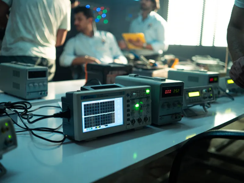
There is a quiet assumption embedded in most electronics workbenches across the country: if a power supply is rated for a given voltage and current, it will deliver that voltage and current. The number on the label becomes a contract. The datasheet becomes a promise. And for a significant number of engineers—students and professionals alike—that assumption holds right up until the moment it fails catastrophically.
Power supply specifications are not lies in the deliberate sense. They are, however, deeply contextual numbers measured under idealized conditions that may bear little resemblance to your actual application. Understanding what those conditions are, and what happens when your circuit departs from them, is the difference between a robust design and one that works perfectly on the bench and fails in the field.
The Conditions Behind the Number
When a manufacturer publishes a voltage regulation figure—say, ±1% from no load to full load—that measurement is typically taken at room temperature, with a purely resistive load, after the unit has reached thermal equilibrium, and often at a single operating point. Real circuits are none of those things.
Your microcontroller wakes from sleep and demands 200 mA in under a microsecond. Your motor driver slams a 3A pulse onto the rail every time the H-bridge switches. Your RF transmitter fires a burst that collapses the supply voltage by 150 mV for just long enough to reset the adjacent logic. None of these events appear in a datasheet's headline specification, yet each one is fully capable of corrupting data, triggering brownout resets, or stressing components into early failure.
The specification you should be reading first is not the voltage accuracy figure. It is the transient response specification—the time required for the output to recover to within a defined tolerance after a step change in load current. For linear regulators, this is often expressed in terms of output capacitance requirements. For switching regulators, it is a function of control loop bandwidth. A supply with a 500 µs transient recovery time is a fundamentally different device from one that recovers in 10 µs, even if both carry identical voltage accuracy ratings.
Ripple: The Noise Floor Your Circuit Lives On
Switching power supplies are efficient, compact, and nearly universal in modern electronics. They are also inherently noisy. The switching action that makes them efficient generates a periodic ripple voltage on the output rail, typically at the switching frequency and its harmonics. Published ripple figures—often in the range of 50 to 100 mV peak-to-peak—are again measured under specific, favorable conditions.
What matters to your circuit is not the ripple at the supply's output terminal. It is the ripple at the power pins of your most sensitive components, after traveling through PCB traces, connector resistance, and whatever bulk and bypass capacitance you have placed along the way. A 50 mV ripple specification can easily become 200 mV at an ADC reference pin if the board layout is careless. For a 12-bit converter operating from a 3.3 V reference, 200 mV of rail noise represents a potential error of roughly 250 LSBs—a figure that renders the converter's specified accuracy completely meaningless.
High-frequency switching noise compounds this problem. Many datasheets quote ripple only at the fundamental switching frequency, omitting the higher-frequency spectral content that bypasses bulk capacitors and couples directly into sensitive analog and RF circuitry. A supply that appears clean on a 20 MHz oscilloscope bandwidth setting may be injecting significant energy at 100 MHz or beyond.
Temperature, Time, and the Drift Nobody Documents
Electrolytic capacitors are the thermal weak point of virtually every switching power supply. Their capacitance, ESR, and lifetime are all strong functions of temperature, and the internal temperature of a loaded supply running in a warm enclosure can easily reach 60°C or higher at the capacitor body. Every 10°C increase in operating temperature roughly halves the expected capacitor lifetime according to the Arrhenius model—a rule of thumb that translates directly into output voltage drift, increased ripple, and eventual failure.
This aging effect is particularly insidious because it is gradual and because most engineers never test their power supply performance after six months of operation. A supply that delivered clean, well-regulated output on day one may be producing significantly degraded performance by the time a product reaches its first annual service interval. Designs that operated with comfortable margins at the prototype stage can find those margins eroded away in deployed hardware.
Dropout voltage is another specification that demands scrutiny beyond the headline number. A linear regulator's dropout voltage—the minimum differential between input and output required for regulation—increases with load current and with temperature. A regulator specified at 300 mV dropout at room temperature and light load may require 600 mV or more at full load in a warm environment. If your input supply is derived from a battery approaching end of discharge, that additional dropout voltage represents the difference between a functioning circuit and one that has lost regulation entirely.
Why a Larger Supply Is Not Always a Safer Supply
The intuitive response to power supply uncertainty is to over-specify. If the circuit needs 300 W, buy a 500 W supply and operate it at 60% load. For thermal stress on the supply itself, this logic has merit. But it introduces a subtler problem: many switching regulators are optimized for efficiency and transient response at or near their rated load. At light loads, control loop dynamics can change, switching frequency may shift, and output impedance can increase. A supply that behaves beautifully at 80% load may exhibit significantly worse transient response and ripple at 30% load—precisely the operating point where you believed you had the most margin.
The correct approach is not to maximize the supply rating relative to the load. It is to characterize supply performance across the actual load range your circuit will demand, including the dynamic extremes, at the temperature extremes your application will encounter.
Measurement as a Design Discipline
None of this is knowable from a datasheet alone. The only reliable path to understanding how a power supply will behave in your specific application is measurement. An oscilloscope with sufficient bandwidth, a current probe, and a programmable load capable of generating realistic step transients will reveal more about your power architecture in an afternoon than months of datasheet study.
Measure ripple at the supply output and at the power pins of your critical components. Apply step load transients that mimic your circuit's actual behavior and observe the voltage excursion and recovery time. Repeat those measurements at the upper end of your expected operating temperature range. Log output voltage over time during extended operation.
The engineers who build genuinely reliable electronics are not those who trust specifications most completely. They are the ones who understand exactly what those specifications mean, where they were measured, and what conditions cause real-world performance to diverge from them. The power supply is not a solved problem you can place outside your design thinking. It is the foundation on which everything else depends, and foundations deserve scrutiny.