Rated to Fail: The Derating Secrets Component Manufacturers Bury in Their Datasheets
Every component on your schematic arrives with a promise printed in its datasheet. A capacitor rated for 50 volts. A transistor with a maximum collector current of 2 amperes. A resistor dissipating up to 0.25 watts. These numbers feel authoritative, even reassuring. They are also, in a very practical sense, fiction.
Not because manufacturers are being dishonest — the numbers are real. They represent what a component can theoretically withstand under carefully controlled laboratory conditions: room temperature, minimal humidity, clean DC signals, and no mechanical stress. The moment that component enters your circuit, all of those conditions change. And when they change, the gap between the rated specification and the actual safe operating limit widens in ways that have ended careers, triggered product recalls, and in some cases, caused fires.
Understanding component derating is not an advanced topic reserved for aerospace engineers. It is a fundamental discipline that every designer — from a student building their first Arduino shield to a professional laying out a power distribution board — must internalize before a single trace is routed.
What Derating Actually Means
Derating is the practice of operating a component at a fraction of its published maximum rating. The underlying principle is straightforward: every electrical component experiences some degree of stress during normal operation. Heat, voltage transients, current surges, and mechanical vibration all accelerate the physical degradation mechanisms inside a component. By deliberately operating below the rated maximum, you slow those mechanisms and extend the functional lifespan of the part.
Most professional design standards — including those published by NASA, the military under MIL-HDBK-338, and major commercial aerospace bodies — mandate specific derating percentages for different component classes. A general-purpose guideline used across the industry recommends operating resistors at no more than 50 percent of their rated power dissipation, capacitors at no more than 50 to 70 percent of their voltage rating, and semiconductors within similarly conservative thermal and electrical boundaries.
These are not arbitrary conservative estimates. They are derived from empirical reliability data collected over decades of field failures.
The Temperature Trap
Of all the variables that erode a component's real-world capability, temperature is the most insidious. Most datasheets publish their maximum ratings at an ambient temperature of 25 degrees Celsius — a comfortable room temperature that describes almost no real operating environment. Inside an enclosure with even modest self-heating, ambient temperatures routinely reach 50 to 70 degrees Celsius. In automotive, industrial, or outdoor applications, they climb higher still.
The relationship between temperature and component reliability is not linear. For electrolytic capacitors, a widely cited rule of thumb — rooted in the Arrhenius equation governing chemical reaction rates — holds that every 10-degree Celsius increase in operating temperature roughly halves the capacitor's expected lifespan. A capacitor rated for 2,000 hours at 85 degrees Celsius that operates continuously at 95 degrees Celsius may deliver only 1,000 hours of service before its electrolyte degrades to the point of failure.
Semiconductors tell a similar story. A voltage regulator with a junction-to-ambient thermal resistance of 50 degrees Celsius per watt, dissipating 1 watt in a 40-degree ambient environment, reaches a junction temperature of 90 degrees Celsius — still within the rated maximum of 125 degrees, perhaps, but already operating in territory where long-term reliability is measurably compromised.
The derating curve buried in the back of most component datasheets quantifies exactly this relationship. It shows how the maximum allowable operating parameter — power, voltage, current — must be reduced as temperature rises. Most designers never look at this curve. That omission is where failures are born.
A Case Study in Capacitor Failure
Consider a real-world scenario that plays out with uncomfortable regularity in consumer electronics. A designer selects a 16-volt electrolytic capacitor for a 12-volt power supply rail, reasoning that a 4-volt margin provides adequate headroom. The design passes bench testing. It ships.
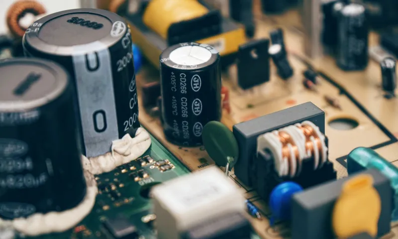
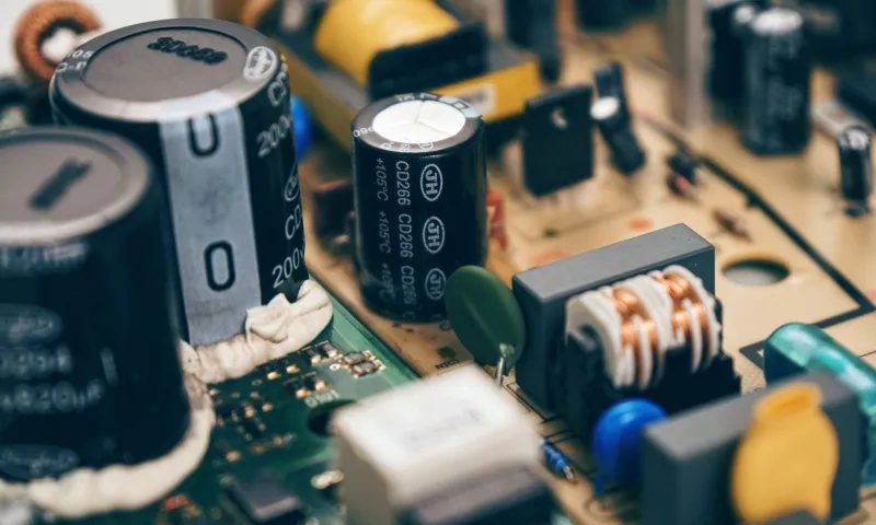
Six months later, field returns begin accumulating. Boards are failing with bulging or leaking capacitors on the power rail. The investigation reveals two compounding factors the original design review never addressed. First, the power supply rail exhibited voltage transients reaching 14.5 volts under switching load conditions — measured only after failures prompted a closer look. Second, the capacitors were mounted near a power transistor that elevated local board temperature to 65 degrees Celsius during normal operation.
At 65 degrees Celsius and with transient voltages approaching 90 percent of the capacitor's rated voltage, the component was operating far outside its derated safe zone. The rated specification was never violated in isolation. The combination of thermal and electrical stress, compounded over time, caused premature dielectric breakdown.
A 25-volt capacitor — which would have cost perhaps two cents more per unit — would have resolved the voltage stress entirely. Better thermal layout would have addressed the temperature contribution. Neither change was made because neither derating consideration was applied during the original design phase.
Resistors: The Most Underestimated Derating Case
Resistors are so simple and so inexpensive that designers frequently treat them as infallible. They are not. A standard 0402-package surface-mount resistor rated at 0.0625 watts is a common sight on modern boards — and a common source of subtle long-term drift failures when operated near its rated power.
At elevated temperatures, resistive films experience thermally driven resistance drift. Carbon composition resistors are particularly susceptible; metal film and wirewound types are more stable but not immune. Operating a resistor continuously at 80 percent of its rated power in a warm enclosure is a reliable recipe for a circuit whose behavior gradually shifts away from its designed parameters over months of field operation — often slowly enough that the drift is attributed to other causes before the resistor is ever examined.
Professional practice dictates that resistors in precision or long-life applications should be derated to 50 percent or less of their rated power dissipation. For high-temperature environments, that figure drops further.
Building Derating Into Your Design Process
The most effective way to apply derating discipline is to make it a mandatory checkpoint in your component selection process, not an afterthought during design review.
Begin by establishing the worst-case operating environment for your design. What is the maximum ambient temperature the enclosure will realistically reach? What transient voltages or current spikes does the circuit generate under switching or startup conditions? What is the expected operational duty cycle?
With those parameters defined, apply derating factors to each critical component. For capacitors, target an operating voltage at or below 50 percent of the rated voltage for long-life applications, and no more than 70 percent for general commercial designs. For semiconductors, verify junction temperatures under worst-case thermal conditions using the thermal resistance data in the datasheet — not the ambient temperature alone. For resistors, size for 50 percent power dissipation in standard designs, and revisit that figure downward for precision or high-reliability applications.
Simulation tools including SPICE can assist with worst-case analysis, but they are only as accurate as the models and boundary conditions you supply. Thermal simulation tools — increasingly accessible even to small design teams — can identify hotspots before a board is ever fabricated.
The Cost of Ignoring the Curves
The financial argument for derating is compelling even before reliability is considered. A field failure carries costs that dwarf the price difference between a properly derated component and its undersized counterpart. Warranty replacement, customer support burden, reputation damage, and potential regulatory scrutiny all accumulate from design decisions that could have been resolved for fractions of a cent per unit at the schematic stage.
For educators and students, derating represents one of the clearest illustrations of the gap between theoretical electronics and the discipline of engineering. A component's datasheet is a starting point, not a destination. The real engineering begins when you ask not what a component can theoretically withstand, but what it can reliably sustain across years of real-world operation — and then design accordingly.