Ghost in the Machine: Diagnosing and Defeating Electromagnetic Interference in Your Electronics Projects
Photo: Jan Helebrant, CC0, via Wikimedia Commons
You have checked the schematic three times. The solder joints look clean. The power supply reads a steady 5V. And yet your microcontroller resets at random, your sensor outputs drift without cause, and your wireless module drops its connection every few minutes. Before you blame the component or the code, consider a culprit that leaves no visible trace: electromagnetic interference.
EMI is the uninvited presence in nearly every electronic system, and for hobbyists and students building on breadboards or custom PCBs, it can transform a promising project into an exercise in frustration. Understanding its origins, recognizing its symptoms, and applying methodical countermeasures will elevate your skills from reactive troubleshooting to deliberate, confident design.
What Electromagnetic Interference Actually Is
At its core, EMI is unwanted electrical energy that disrupts the intended operation of a circuit. It travels through two primary pathways: conducted interference, which moves along power lines and ground connections, and radiated interference, which propagates through the air as electromagnetic waves. Both can corrupt digital signals, introduce noise into analog measurements, and cause logic errors that appear entirely random.
Sources are everywhere. Switch-mode power supplies generate high-frequency switching noise. DC motors and relays produce transient spikes when their inductive loads collapse. Nearby Wi-Fi routers, fluorescent lighting, and even the fast edges of digital clock signals inside your own circuit can radiate enough energy to upset sensitive components. In a home workshop environment — surrounded by appliances, wireless devices, and unshielded cabling — the electromagnetic landscape is remarkably crowded.
The challenge is that EMI often mimics other problems. A microcontroller that resets unpredictably could suggest a firmware bug, a voltage regulator issue, or a marginal decoupling capacitor. Without a framework for identifying interference specifically, engineers and hobbyists frequently chase the wrong root cause for hours or days.
Recognizing the Symptoms
Certain behavioral patterns point strongly toward EMI as the underlying cause. Random resets in microcontrollers, especially when motors or relays switch on nearby, are a classic indicator. Analog sensors — accelerometers, temperature probes, audio inputs — that show noise correlated with the operation of other equipment in the room suggest radiated pickup. Serial communication errors that appear only under certain operating conditions often trace back to ground loops or conducted noise on shared power rails.
One practical diagnostic technique involves temporal correlation. Keep a log of when malfunctions occur and note what else is happening in the environment at that moment. If a particular appliance cycling on and off coincides with your circuit's erratic behavior, you have identified a likely aggressor. Another approach is to power your circuit from a battery rather than a wall adapter and observe whether the problem persists. If it disappears on battery power, conducted noise from the AC supply is a strong candidate.
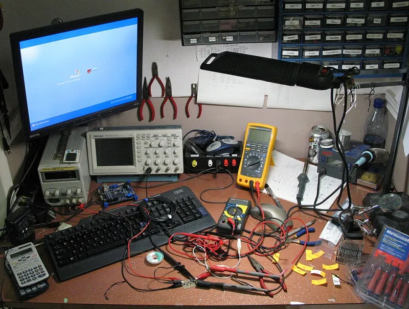
An oscilloscope is invaluable here. Probing your power rails during a malfunction often reveals voltage spikes or high-frequency ripple that a multimeter would never capture. Even an inexpensive entry-level oscilloscope — a worthwhile investment for any serious hobbyist — can expose interference that would otherwise remain invisible.
Practical Shielding and Layout Strategies
Once you have identified interference as the problem, the solution set is well-established, even if applying it requires some discipline and experimentation.
Decoupling capacitors are the first line of defense against conducted noise. Placing ceramic capacitors — typically 100nF — as close as physically possible to every power pin on every IC ensures that local charge is available to smooth out transients before they propagate. Many beginners place these capacitors too far from the component or omit them entirely, leaving the power rail vulnerable to high-frequency disturbances.
Ground plane design is equally important, particularly on custom PCBs. A continuous copper ground plane on one layer of a PCB dramatically reduces the impedance of the return current path, which in turn reduces the loop area that acts as an antenna for both radiating and receiving interference. On a breadboard, this effect can be partially replicated by using thick, short wires for ground connections and minimizing the area of any loop formed between a signal wire and its return path.
Physical separation and routing discipline matter more than many beginners appreciate. Keeping high-speed digital signals away from sensitive analog inputs, routing clock lines away from communication buses, and avoiding running power and signal wires in parallel over long distances all reduce coupling between aggressor and victim circuits.
Shielding enclosures provide a physical barrier against radiated interference. Metal enclosures — aluminum project boxes are widely available and affordable — attenuate electromagnetic fields that would otherwise reach sensitive circuitry inside. For this to be effective, the enclosure must be properly grounded; a floating shield can actually concentrate interference rather than divert it.
Ferrite beads are small, inexpensive components that act as frequency-dependent resistors, absorbing high-frequency noise on power and signal lines without significantly affecting DC or low-frequency operation. Adding a ferrite bead in series with a power supply line entering a sensitive module is a quick and effective mitigation step.
Working With Wireless Systems
Projects that incorporate Bluetooth, Wi-Fi, or other RF modules introduce a unique EMI challenge: the module itself is both a potential aggressor and a victim. A poorly designed power supply can inject noise directly into the RF front end, degrading range and reliability. Conversely, fast-switching digital logic near the antenna can desensitize the receiver.
For these builds, antenna placement deserves careful attention. Keep the antenna away from metal structures, motor drivers, and switching regulators. Use a dedicated power regulator for the RF module rather than sharing a rail with high-current loads. Many popular development boards, including those based on the ESP32 and nRF52 families, include guidance in their datasheets on recommended keep-out zones around the antenna — guidance that is easy to ignore but costly to disregard.
Building Better Habits From the Start
The most effective approach to EMI is not remediation after the fact but prevention built into the design process. Before laying out a PCB or wiring a prototype, consider the current paths in your circuit. Ask where high-frequency currents will flow, what loops they will form, and which sensitive nodes might be in proximity to those paths.
Consulting application notes from component manufacturers is one of the most underutilized resources available to hobbyists and students. Texas Instruments, Analog Devices, and Microchip Technology, among others, publish detailed guidance on PCB layout and EMI mitigation for their specific products — guidance developed through extensive testing and real-world validation.
Electromagnetic interference will never be fully eliminated from any real-world electronic system. The goal is management: reducing interference to a level that no longer affects circuit operation. With a structured diagnostic approach, an understanding of how energy couples between circuits, and a toolkit of proven countermeasures, what once seemed like mysterious and random failure becomes a solvable engineering problem. That shift in perspective is what separates a builder who gets lucky from one who gets it right.