The Logic Analyzer: Why This Overlooked Instrument Belongs on Every Maker's Bench

Photo by Photo by Jorge Ramirez on Unsplash on Unsplash
For decades, the multimeter has occupied the center of the hobbyist workbench — measuring voltage, continuity, and resistance with quiet reliability. It is a tool that rewards patience and teaches fundamental circuit behavior. But as the projects tackled by students and makers have grown considerably more sophisticated, the multimeter has begun to show its limits. When a microcontroller refuses to communicate with a peripheral, or when an I2C bus hangs unexpectedly at 3 a.m., a voltage reading of 3.3 volts tells you almost nothing useful.
That is where the logic analyzer earns its place.
What a Logic Analyzer Actually Does
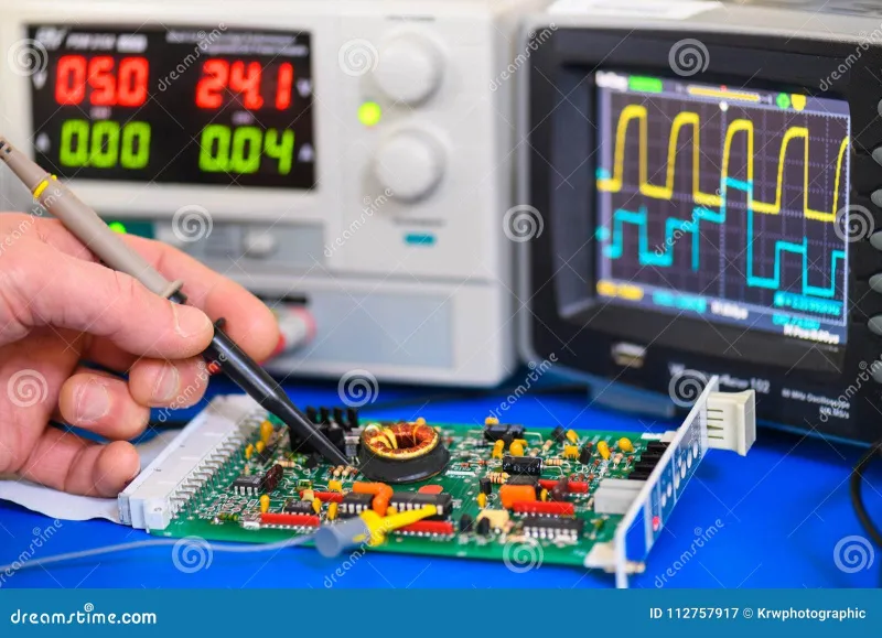
At its core, a logic analyzer captures the state of digital signals over time and displays them as waveforms on a timeline. Where a multimeter samples a single point and returns a value, a logic analyzer records sequences of ones and zeros across multiple channels simultaneously, allowing you to see precisely when signals change, how long they remain in a given state, and how multiple signals relate to one another in time.
For embedded systems work — which now dominates the maker community — this temporal dimension is everything. Protocols such as UART, SPI, I2C, CAN, and USB are fundamentally time-dependent. A byte sent over UART is nothing more than a carefully timed sequence of high and low states. If the timing is off by even a small margin, the receiving device misinterprets the data or drops the transmission entirely. No multimeter, regardless of its price or precision, can reveal that kind of failure.
The Price Barrier Has Effectively Disappeared
For much of the instrument's history, logic analyzers were expensive laboratory tools reserved for professional engineers working at well-funded companies. That reality has changed substantially. Today, capable eight-channel USB logic analyzers — compatible with the widely used open-source Sigrok and PulseView software — are available for well under thirty dollars from domestic and international suppliers. Devices in the fifty to one-hundred-dollar range offer sixteen or more channels, higher sample rates, and polished companion software with built-in protocol decoders.
For context, many hobbyists spend more than that on a single microcontroller development board or a spool of quality solder. The cost argument against adding a logic analyzer to the bench has largely evaporated.
A Real Debugging Scenario: I2C Communication Failure
Consider a scenario familiar to anyone who has worked with sensor modules. You wire an environmental sensor to an Arduino or Raspberry Pi, load the library, run the example sketch, and the serial monitor returns nothing but zeros or an outright error. The multimeter confirms power is reaching the sensor — 3.3 volts on VCC, ground confirmed, pull-up resistors in place. Everything looks correct. The project stalls.
Attach a logic analyzer to the SDA and SCL lines, however, and the problem often becomes immediately visible. You might observe that the clock line is not toggling at all, indicating the microcontroller's I2C peripheral failed to initialize. Alternatively, you might see the start condition issued correctly but no acknowledgment returned — a sign that the sensor's address in the code does not match the hardware configuration. In some cases, you will find that the pull-up resistors are too weak for the bus speed selected, causing the signal edges to slope gradually rather than transition sharply, producing intermittent read errors that would be nearly impossible to diagnose any other way.
Each of these failure modes produces a distinct visual signature in the logic analyzer's waveform view. What might consume an entire afternoon of guesswork resolves in minutes.
Protocol Decoding Changes the Conversation
Modern logic analyzer software does not simply display raw waveforms. Protocol decoders translate captured bit sequences into human-readable annotations displayed directly on the timeline. An SPI transaction becomes a labeled series of register addresses and data values. A UART stream resolves into ASCII characters or hexadecimal bytes. An I2C exchange shows device addresses, read and write flags, and acknowledged or unacknowledged packets — all rendered visually alongside the underlying signal.
This capability is transformative for learning. Students working through embedded systems coursework can observe exactly how a protocol behaves in practice, reinforcing textbook descriptions with empirical evidence from their own hardware. The gap between reading a datasheet and understanding what is actually happening on the bus closes considerably when you can watch every transaction unfold in real time.
Where the Multimeter Still Wins
None of this should suggest that the multimeter is obsolete or unnecessary. For power supply verification, continuity testing, component identification, and analog circuit debugging, it remains indispensable. A logic analyzer cannot tell you whether a decoupling capacitor has failed, whether a trace is carrying the correct supply voltage, or whether a resistor has drifted out of tolerance. These instruments are complementary rather than competitive.
The practical recommendation is straightforward: reach for the multimeter first when diagnosing power, continuity, or analog signal issues. Reach for the logic analyzer the moment the problem involves digital communication, timing, or protocol behavior. Knowing which tool fits the problem cuts debugging time dramatically.
Building the Skill Before the Need Arises
One of the most valuable habits a developing engineer or serious hobbyist can cultivate is learning an instrument before a crisis demands it. Connecting a logic analyzer to a working project — one that is functioning correctly — and observing normal protocol behavior builds the pattern recognition needed to identify abnormal behavior quickly when something breaks. What does a healthy I2C transaction look like? How does SPI behave during a multi-byte transfer? Answering those questions on a working system makes the answers available when the system stops working.
Sigrok's PulseView software, available free for Windows, macOS, and Linux, is an excellent starting point. Its documentation is thorough, its protocol decoder library is extensive, and its interface is accessible to newcomers without being condescending to experienced users.
The Broader Lesson for Modern Makers
The increasing prevalence of microcontrollers, wireless modules, sensor arrays, and communication peripherals in hobbyist projects reflects a genuine shift in what the maker community builds. Projects that once consisted of discrete components and analog circuits now involve layered software stacks, multi-device communication buses, and real-time timing constraints. The instrumentation used to debug these systems needs to evolve alongside the projects themselves.
The logic analyzer represents that evolution. At a price point accessible to students on a budget, with software sophisticated enough to serve professionals, and with a learning curve shallow enough to navigate in a single weekend session, it has become one of the most practical additions available to the modern electronics workbench. The only remaining question is why it took this long to become a standard recommendation.