Microcontrollers Never Truly Sleep: Mastering Leakage Current for Long-Life Battery Designs
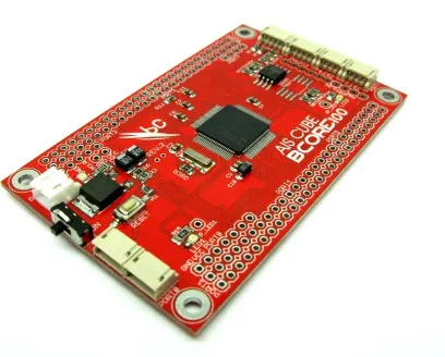
Photo: Onorai, CC BY-SA 3.0, via Wikimedia Commons
There is a persistent myth in embedded systems development: put the microcontroller to sleep, and the battery stops draining. In practice, the situation is considerably more nuanced—and considerably more consequential. A microcontroller placed in its deepest sleep mode still draws current. Sometimes that figure is a few hundred nanoamps. Sometimes it is several microamps. In a device powered by a coin cell rated at 220 mAh, even a steady 2 µA of leakage will exhaust the battery in roughly 12 years—which sounds acceptable until you add in every other component on the board. The cumulative picture tells a very different story.
For students entering the field of embedded systems, and for professionals transitioning into IoT or wearable design, leakage current is the discipline's most underestimated adversary. It does not trigger alarms. It does not cause obvious malfunctions. It simply shortens product life, frustrates end users, and erodes brand trust—often before anyone identifies the real cause.
What Leakage Current Actually Is
At the semiconductor level, leakage current refers to current that flows through a device even when it is nominally switched off or in a non-conducting state. Several distinct mechanisms contribute to this phenomenon.
Subthreshold leakage occurs in MOSFET transistors when the gate voltage falls below the threshold voltage. Modern process nodes—the 40 nm, 28 nm, and smaller geometries common in today's microcontrollers—have dramatically reduced transistor size, which unfortunately increases subthreshold leakage as a side effect. The physics are unavoidable: smaller gate oxides and shorter channel lengths allow more current to sneak through even when the transistor is theoretically off.
Reverse-biased junction leakage appears at every p-n junction within the device. When a diode or transistor junction is reverse biased, it should ideally block all current. In reality, thermally generated minority carriers allow a small but nonzero current to flow. This leakage increases significantly with temperature—a factor that catches many designers off guard when their device is deployed outdoors in a Southern summer.
Gate oxide tunneling is a quantum mechanical effect in which electrons tunnel directly through the extremely thin gate insulator. This mechanism becomes increasingly significant below 3 nm oxide thicknesses and is a growing concern in the latest process nodes.
For practical embedded design purposes, the combined effect of all these mechanisms is captured in the datasheet figure labeled "IDD in Sleep" or "Supply Current in Power-Down Mode." Reading that number carefully—and skeptically—is the first step.
Reading Datasheets Like an Engineer, Not a Beginner
Datasheet leakage figures are measured under specific, often idealized conditions. A microcontroller might specify 100 nA of sleep current at 25°C with all peripherals disabled and all GPIO pins properly configured. Each of those qualifiers carries real engineering weight.
Temperature dependence is critical. Junction leakage roughly doubles for every 10°C rise in temperature. A device drawing 100 nA at 25°C may draw 400 nA or more at 65°C—a temperature easily reached inside a sealed enclosure on a warm day. Designers targeting outdoor or automotive-adjacent applications must account for this in their power budget.
GPIO pin state is another frequently overlooked variable. Floating input pins that oscillate between logic levels can cause the internal protection diodes and input buffers to draw current continuously. Before entering sleep mode, every unused GPIO should be explicitly driven to a defined state—either logic high or logic low—or configured as an output held at a stable level. This single discipline fix has rescued more than a few shipping products from premature battery failure.
Peripheral clocks that remain enabled during sleep are another common culprit. Many microcontroller families allow individual peripheral clock gates to remain active even in low-power modes unless explicitly disabled in firmware. Reading the power management chapter of a reference manual—not just the quick-start guide—is non-negotiable for serious low-power work.
Building a Leakage Budget
A leakage budget is a systematic accounting of every current-drawing element in a battery-powered design during its quiescent state. The process mirrors the discipline of a power engineer calculating load flow—every node matters.
Start by listing every active component: the microcontroller, any connected sensors, voltage regulators, communication modules, and passive networks. For each, identify the sleep-mode or off-state current from the datasheet, adjusted for operating temperature. Sum these figures to arrive at your baseline quiescent draw.
As a worked example, consider a simple environmental sensor node:
- Microcontroller in deep sleep: 500 nA
- LDO voltage regulator quiescent current: 3,500 nA (3.5 µA)
- Humidity sensor in standby: 800 nA
- Pull-up resistors on I²C lines (3.3 V through 10 kΩ each, two lines): 660,000 nA (660 µA)
The pull-up resistors dominate the budget entirely—a stark illustration of how passive components can dwarf semiconductor leakage. The solution is to switch the pull-up resistors off via a GPIO-controlled load switch or to use an I²C bus with internal pull-ups that can be disabled in firmware before sleep entry.
With the resistors addressed, total quiescent draw falls to approximately 4.8 µA. A 1,000 mAh AA lithium cell would theoretically power the sleep state alone for over 23 years—though active-mode wake cycles, self-discharge, and real-world temperature variation will reduce that figure substantially.
Practical Measurement Techniques
Calculating a leakage budget on paper is valuable, but measurement is essential. Microamp-level currents require instrumentation beyond what a standard benchtop multimeter can reliably deliver. A precision source-measure unit (SMU) such as the Keysight B2900 series or a dedicated low-current ammeter placed in series with the supply rail provides the accuracy needed.
For lab environments on a tighter budget, a high-value sense resistor (10 kΩ to 100 kΩ) placed in the supply path, combined with a quality digital multimeter measuring the voltage drop, can resolve currents in the low-microamp range. The tradeoff is a slight reduction in supply voltage to the device under test—acceptable for characterization, but not for final validation.
Oscilloscope-based current measurement using a current probe or a low-value shunt resistor (1 Ω to 10 Ω) is invaluable for capturing the dynamic current profile during sleep entry and wake transitions. These transient events often reveal spurious current spikes caused by incomplete peripheral shutdown or clock glitches—problems invisible to a DC ammeter.
Design Strategies That Make a Measurable Difference
Beyond careful GPIO management and peripheral gating, several architectural choices meaningfully reduce leakage in production designs.
Load switching places an external MOSFET or dedicated load switch IC between the supply rail and power-hungry peripherals. When the microcontroller sleeps, it disables the switch, cutting off the peripheral entirely. This is the most effective technique for sensors and communication modules that draw significant standby current.
Choosing the right regulator matters enormously. Many LDO regulators carry quiescent currents measured in microamps to milliamps. Switching to a nanopower LDO—devices from Texas Instruments, Microchip, and Analog Devices offer options below 1 µA—can reclaim significant budget headroom.
Selecting process-appropriate microcontrollers is a design-level decision. Families such as the Nordic Semiconductor nRF52 series, the STMicroelectronics STM32L series, and the Ambiq Micro Apollo series were architected specifically for ultra-low-power operation, with sleep currents measured in the hundreds of nanoamps rather than microamps.
Mastering leakage current is not glamorous work. It involves careful datasheet analysis, methodical measurement, and disciplined firmware habits. But for engineers and students who commit to understanding it, the reward is devices that genuinely perform as promised in the field—and a professional competency that distinguishes thoughtful designers from those still wondering why their prototype battery only lasts three weeks.