The Oscilloscope Is Not Optional: Why Analog Measurement Mastery Defines the Truly Skilled Engineer
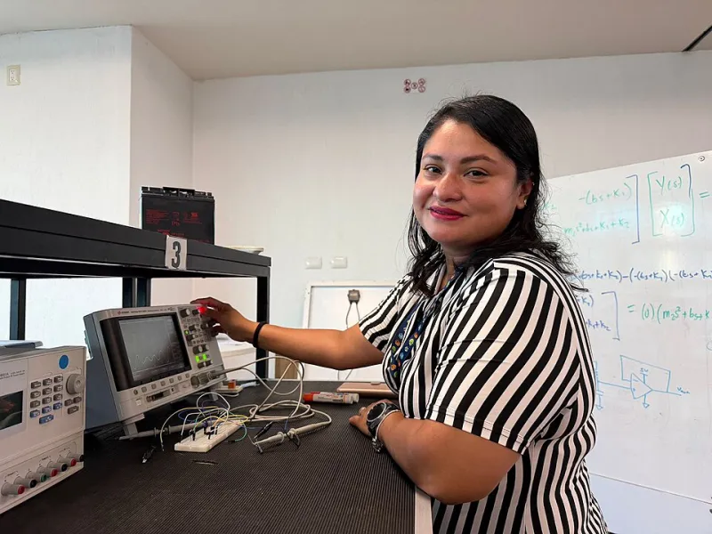
Photo: AmmyLucio, CC BY 4.0, via Wikimedia Commons
Walk into any serious electronics lab in the United States—a university research facility, a hardware startup in Austin, a defense contractor outside Boston—and you will find oscilloscopes. Not tucked in a cabinet as legacy equipment, but front and center on active benches, their traces flickering with the real-time behavior of circuits that no simulation has perfectly predicted. The oscilloscope has been a fixture of electronics engineering for the better part of a century, and despite every digital revolution that has reshaped the field around it, it has not been displaced. There is a reason for that.
The argument that modern software tools have made oscilloscope skills optional is understandable. Simulation environments like SPICE and its many descendants are extraordinarily powerful. Protocol analyzers decode I²C, SPI, CAN, and USB transactions with a few mouse clicks. Mixed-signal oscilloscopes blur the line between analog and digital capture. And yet, the engineer who cannot sit down at a scope, configure it correctly for the measurement at hand, and accurately interpret what the display is showing remains fundamentally limited—regardless of how sophisticated their software toolkit has become.
The Physics Does Not Negotiate
The core reason oscilloscope mastery remains irreplaceable is straightforward: real circuits operate in the physical world, and the physical world does not conform to schematic ideals. Every wire is an inductor. Every trace capacitance is a filter. Every power rail carries noise. Every logic transition overshoots, rings, and settles according to the actual impedance environment it encounters.
Simulation can model these effects if you know they exist and take the time to characterize them. But the oscilloscope reveals them whether you expected them or not. That asymmetry is enormously valuable. The scope is, in a meaningful sense, an unbiased witness to circuit behavior—it shows you what is actually happening rather than what your model predicted.
This is not a trivial distinction. Countless product failures, from consumer electronics to medical devices, have traced back to signal integrity problems that were invisible in simulation and only apparent when someone finally connected a probe to the right node at the right moment. The engineer who can do that fluently—who knows where to look, how to trigger, and what the waveform is telling them—is worth considerably more than one who cannot.
Trigger Modes: The Underutilized Superpower
Among the oscilloscope's most powerful and most underused capabilities is its triggering system. A beginner typically learns edge triggering early: set the trigger to rising edge on channel one, adjust the level, and the waveform stabilizes on screen. That is a useful starting point and an inadequate stopping point.
Pulse-width triggering allows the instrument to capture only those events where a signal pulse is narrower or wider than a specified duration. This is invaluable for isolating occasional glitches on a data bus—events that occur perhaps once every several thousand cycles and are completely invisible to edge triggering. Without pulse-width triggering, finding such a glitch by eye is essentially impossible. With it, the oscilloscope can be configured to wait patiently until the anomaly occurs and then capture it automatically.
Pattern triggering takes this further, allowing capture based on a specific logical combination across multiple channels. Runt triggering catches pulses that cross one threshold but fail to cross a second—a classic symptom of marginal signal swing caused by supply noise or impedance mismatch. Timeout triggering captures conditions where a signal fails to transition within an expected window, which is particularly useful for debugging communication timeout faults.
Professional engineers use these modes routinely. They are not obscure features reserved for specialists—they are the tools that make intermittent fault diagnosis possible. The hobbyist who has never explored beyond edge triggering is operating the instrument at perhaps twenty percent of its capability.
Bandwidth, Probes, and the Measurement You Think You Are Making
One of the most consequential misunderstandings among less experienced practitioners is the assumption that the waveform on the oscilloscope display accurately represents the signal at the probe tip. It frequently does not—and the discrepancy can be significant enough to lead to entirely wrong conclusions.
Oscilloscope bandwidth is defined as the frequency at which the instrument's amplitude response has fallen to 70.7 percent of its true value (the -3 dB point). A 100 MHz oscilloscope will display a 100 MHz sine wave at roughly seventy percent of its actual amplitude. For accurate amplitude measurements of signals near the instrument's bandwidth limit, a common engineering rule of thumb calls for five times the bandwidth margin—meaning a 100 MHz scope should only be trusted for signals up to approximately 20 MHz if amplitude accuracy matters.
For digital signals, the relevant frequency is not the fundamental clock rate but the harmonic content of the rise and fall times. A 10 MHz square wave with 5 ns rise times contains significant energy well into the hundreds of megahertz. Attempting to capture and interpret that signal on an inadequately specified scope will yield a distorted, rounded waveform that tells you very little about actual signal integrity.
Probe selection compounds these effects. The default 10x passive probe included with most oscilloscopes introduces its own capacitance—typically 10 to 15 pF—which loads the circuit under test and rolls off high-frequency content. Active probes with input capacitances below 1 pF are necessary for accurate measurements in high-speed digital or RF circuits. And every passive probe requires compensation: a simple adjustment using the built-in calibration square wave that corrects for capacitive mismatch between the probe and the oscilloscope input. Neglecting probe compensation is one of the most common errors on student and hobbyist benches, and it introduces frequency-dependent amplitude errors that corrupt every subsequent measurement.
What Software Cannot Replace
It is worth addressing the digital tools argument directly, because it is not without merit. Modern protocol analyzers are genuinely excellent at decoding structured communication. Automated test equipment can characterize a device across thousands of operating conditions faster than any human operator. Post-processing software can apply FFT analysis, jitter decomposition, and eye diagram generation to captured waveforms.
But all of these tools depend on the engineer first acquiring a valid, representative signal. Garbage in, garbage out—the principle applies with particular force to measurement. An engineer who does not understand bandwidth limitations may acquire a signal that appears clean and well-behaved while the actual circuit is ringing violently on every edge. An engineer who does not understand ground lead inductance may introduce measurement artifacts that look like real circuit behavior. Software has no way to distinguish between a faithful measurement and a corrupted one; that judgment belongs to the human operating the instrument.
There is also the matter of diagnostic intuition—the ability to look at an unexpected waveform and form a rapid, well-grounded hypothesis about its cause. This skill develops through accumulated hands-on experience with real circuits and real instruments. It cannot be downloaded or simulated. It is built slowly, one measurement at a time, by engineers who take the oscilloscope seriously as a precision instrument requiring genuine expertise.
A Skill Worth Investing In
For students in electronics and electrical engineering programs across the country, the oscilloscope lab is often treated as a checkbox exercise—something to survive rather than master. That attitude carries a professional cost that compounds over time. The engineers who treat early oscilloscope experience as an opportunity to build genuine measurement fluency arrive in industry with a capability that is immediately productive and visibly differentiating.
For working professionals who learned the basics and moved on, there is meaningful value in returning to the instrument with fresh curiosity. Exploring advanced trigger modes, experimenting with different probe types, and deliberately practicing on circuits where the expected and actual behavior differ—these habits sharpen diagnostic skills that no amount of software proficiency can replicate.
The oscilloscope is not a relic. It is the most direct window into the behavior of real electronic systems that engineers possess. Treating it as such is not nostalgia for an analog past. It is a commitment to understanding circuits as they actually exist—in the physical world, where the physics does not negotiate.